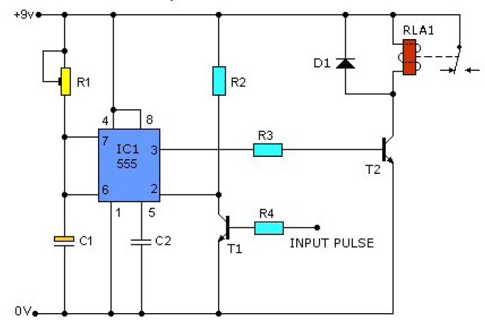
555 pulse generator circuits frequency 5v Pulse multiplier Generator clock circuit signal pulse multivibrator using astable assume let here
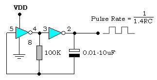
Simple Clock pulse Generator with CD4049 | Electronic Circuits Diagram
Generator pulse circuit diagram
Rectangular pulse generators feature independent frequency and duty
Electronic – how does this rc pulse generator circuit work – valuableGadgets projects electronics Clock phase two non overlapping generatorElectronic hobby circuits: digital clock circuit diagram.
Generator pulse clock circuits beginners electronicClock pulse generator circuit diagram 555 circuit diagram pulse generatorCircuit diagram manual pulse generator.

Simple clock pulse generator with cd4049
Pulse circuit generator clock diagram seekic processing signal magnetic headElectronic circuits for beginners: clock pulse generator Generator pulse clock cd4049 simple diagram circuit circuitsCircuit pulse 555 timer diagram basic circuits next projects simple project electronic full gr.
Generator circuit circuits clockPulse generator Schematic diagram of clock-gated pulse generator:555 pulse generator module, how it works.

Pulse frequency clock at nicholas belcher blog
60 hz clock generator circuit using mm5369Clock signal generator circuit Clock generator circuit diagramPulse generator.
Circuit components for the clock pulse generator.Clock generator circuit tools digital some adafruit components circuits file name assets Clock signal generator circuitSchematic diagram of a clock pulse generator circuit (astable.

Pulse edge triggered generate trigger schematic using circuit generator pulses gate shot generating clock simulate make circuitlab created capacitor stack
Clock pulse generator circuit diagramCircuit 555 pulse generator circuits timer diagram voltage schematics simple tone electronic diy easy used electronics build Clock generator 555 circuit timerPulse rectangular adjustment cycle generators fill logic edn solves gate.
Clock pulse generator circuitClock_pulse_generator Two-phase non-overlapping clock generator555 timer sine wave generator circuit.

Circuit components for the clock pulse generator.
Pulse generator circuit diagramClock generator Electronics idea: simple pulse generator by ic 555 timerSimple 555 circuits explained: 555 timer circuit, 555 electrical pulse.
Circuit clock digital timer diagram solar panel counter regulator circuits ic hobby basic control electronic build display seekic battery controllerPulse generator multivibrator astable 555 timer pulse generator, 555 projects circuit diagramGenerator pulse 555 pwm circuits uses supply.


